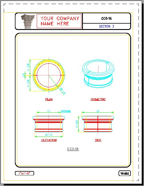
2) Next, the drawing is annotated.
Then the drawing is aligned with PaperSpace, and the scale-factor is filled-in (along with the part name), and printed.
Using proprietary software, the line-type is set, and the drawing is printed.
The drawings will always have the same size annotations, in EVERY DRAWING, no matter what the scale difference is.
Holes are punched, and the drawing is ready for the Catalog!
(Drawings are printed in black, using DansMark's version of pen assignments, or the customer can provide the pen-assignment, ".pc3" file)

3) It requires lots of time & skill to draw this drawing fast & accurate.
Dansmark Software Solutions uses proprietary programming to create catalog drawings quickly.
Incorporating the use of PaperSpace/ModelSpace, the drawing is "set-to-scale", by aligning the "Model" in ModelSpace, with the "Title-Border" in PaperSpace!
This insures accurate "to-scale" drawings, no matter what size the objects are, every time!
Dansmark Software Solutions uses proprietary programming, to create the "Catalog Part Programs", that let the Cad Designer see the objects being used in their drawings.
CatalogPartMaster searches the specified catalog directories, for drawings to create slides from, then CalalogPartMaster creates a ".dat" file of the available drawings found in each directory.
A script is auto-generated from the .dat file. The script cycles through all 9 directories, opening each drawing, creating a picture (.sld) to be used in that directory's "Catalog Part Program".
Then a ".lsp" (Autolisp), and a ".dcl" (Dialog-Control-Language), program is auto-generated, for the original ".dat" file.
Each directory has it's own unique set of shapes.
For example:

You provide the "directory-tree" (a list directories, where you want your parts stored).
There are some charaters that can't be used in the directory-tree (ask for details).
4) This is a sample of the Baluster catalog program.
Using BalusterMachine as the example
There are up to 9 different views of each part, that can be inserted into your drawing.
There are 2 ways to view the next available parts in the Baluster directory:
1) Pick the "image" to cycle to the next available part image.
2) Pick the "drop-down list-box", to view all the available images at once.
Just find the shape you want to use, then pick the view.
Next pick the "OK" button, and the program inserts the block for you.

This Baluster program, will allows the user to auto-place the front/top-view, with as many balusters as can fit between 2 picked points (see below).

Just pick the left-side start-point, then, the right-side end-point, and the program calculates how many balusters are needed to fill the space (fully).
(This part view was picked, inserted, and copied in less than 3 seconds).

Next, pick the top-view from the Baluster dialog, the 2 alignment points, and you have the top view done.
(Additional programming to create multiple balusters systems is extra... ask for details!)

Fast & simple! The DansMark way!
This is just a "sample" of the many parts that can be created, and made into "Catalog-Programs".
The only limitation, is your imagination!
Call or email DansMark Software Solutions today for a free quote!
DansMark Software Solutions
Lake City, Florida. 32025
(386) 243-1981